GitHub Repository: github.com/openxc/simple-hud
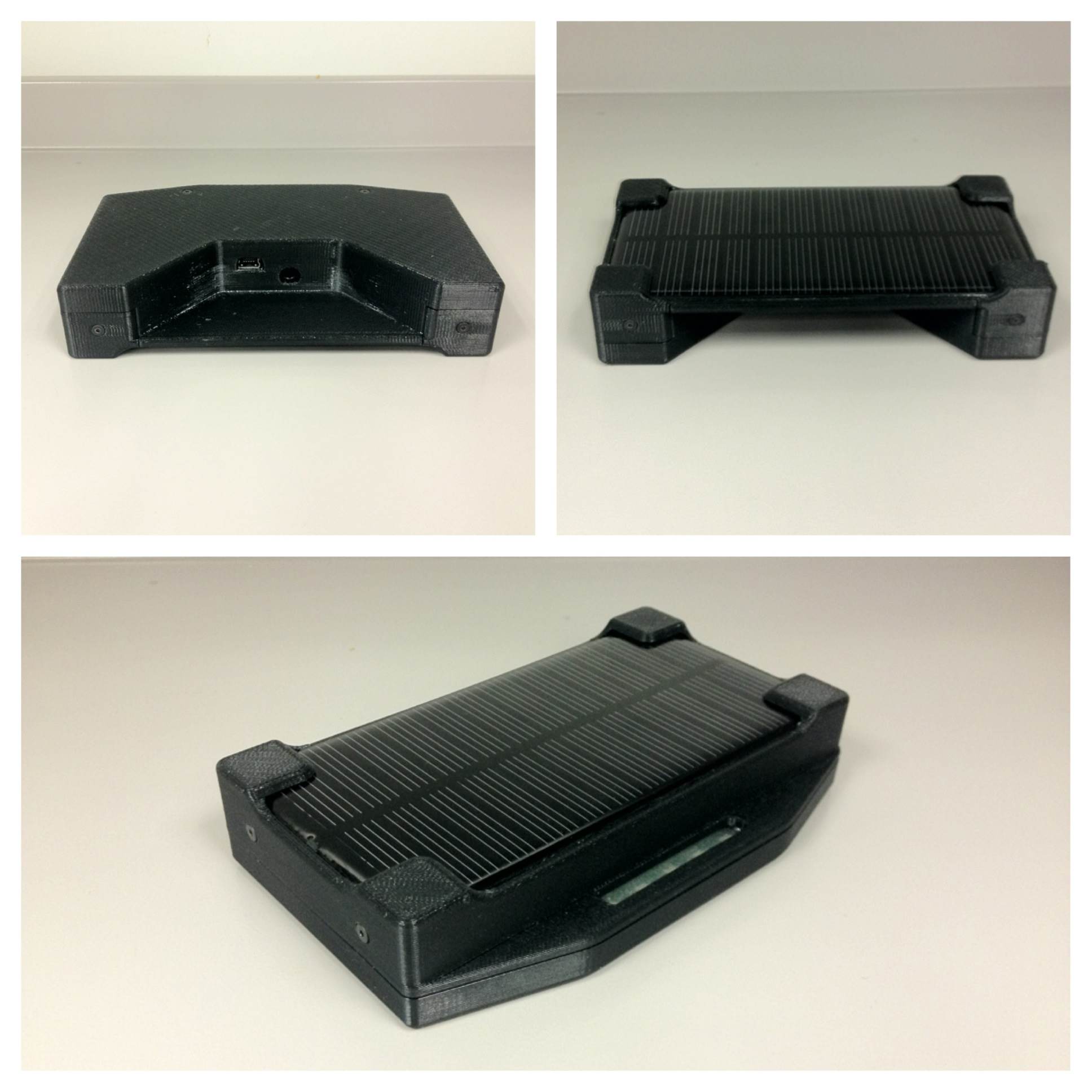
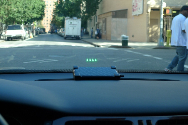
The Bluetooth HUD is a wireless, solar-powered display module to be used inside the vehicle cockpit. The system uses LEDs reflecting off of the windshield to send signals to the driver who can keep his hands on the wheel and his eyes on the road. In the picture shown below, the Bluetooth HUD is being used show real-time fuel efficiency.
The Bluetooth HUD microcontroller responds to serial commands sent from any Bluetooth master (i.e. the host device) and operates the 5 green LEDs accordingly. The Bluetooth HUD has an internal Li-Ion battery which should last between 6 and 40 hours depending on how many LEDs are lit. The battery will be continuously charged by the solar panel if in the presence of sunlight. If a faster charge is needed, there is a USB Mini port on the bottom of the unit. It can be plugged into any computer USB port or AC USB power adapter. The unit will consume up to ~500mA of current to charge it’s internal battery.
The Bluetooth HUD is controlled by IC2, an ATMEGA 328P 8-bit microprocessor. The ATMEGA communicates with a PC, Phone or Tablet (the host device) using Bluetooth via IC1. IC1 is a Roving Networks RN-42, a common embedded Bluetooth IC. They communicate using a serial UART bus. When a host connects to the RN-42, it transparently relays serial data between the ATMEGA and the host device.
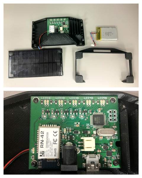
The ATMEGA is connected to LED1-5 using arduino pins 3,5,6,9 and 10, or PORTD3,5,6 and PORTB1,2. The LEDS are lit using generic NPN transistors Q2-6, since the specified LEDs are high-intensity and require too much current for the pins on the ATMEGA. Note that the values of R1-R10 depend on the desired intensity level. 75 ohms is a conservative value - to get maximum intensity out of the specified LEDs we needed to use 0 ohm jumpers.
Capacitors C1 and C4 allow the ATMEGA to be remotely reset by briefly asserting the DTR or CTS lines of the RN-42. With the accompanying bootloader, this allows the ATMEGA to function like a Bluetooth arduino. The first time an Bluetooth HUD board is assembled, the arduino bootloader needs to be installed. This can be accomplished with an AVR programmer and the ICSP port (J1). As long as the RN-42 is correctly configured (see above), code can be deployed to the ATMEGA.
The AVR, RN-42 and LEDs are all powered by a lithium-ion battery connected to JP1. The battery power is regulated to 3.3v by U2, a boost converter. This allows us to drain the maximum amount of power from the battery without damaging it (the regulator has a 2.6V cutoff). The battery can power the circuit for many hours depending on the LED usage (anywhere from 6-40 hours).
The battery can be charged from either a USB Mini power source or the attached solar panel. The USB power source is the optimal way to charge the battery - it will charge at the maximum rate of 500mA provided that much power is available. The DC jack is designed to be used with a 6V solar panel like those available from Adafruit.com. The Li-Ion charger (U1, an MCP73831) isn’t designed to take power from a variable impediance source like a solar cell, but with a large input cap (C9) the circuit is reasonably good at harvesting solar power. See ladyada’s writeup on MPPT for her solarlipo charger project (http://ladyada.net/products/usbdcsolarlipo/design.html).
With the small solar panel installed on the Bluetooth HUD, we measured between 100-200mA under direct sunlight. A larger solar panel would be able to get closer to the 500mA maximum charge rate. If all of the LEDs are fully lit all the time, the LED board needs to be under direct sunlight in order to actually charge the battery.
The HUD is exposed in Android via an in-process service. Take a look at the HudTestActivity for an example of how to use it - the test runs a KITT-style LED fade on the HUD.
To build and deploy the test app to an attached Android device, make sure you have Maven installed and run:
$ cd java
$ mvn install && mvn -pl test android:deployIn Android, you will need to pair and authenticate with the HUD at least once
before it can be used with the HudService. The service doesn’t attempt to do
any authentication at the moment, so it must be done by hand.
When powered on, the unit will be a discoverable Bluetooth device. In the Android “Bluetooth Settings” activity, you should be able to scan for an find a device named “RN42-XXXX” where XXXX is the last 4 digits of the unit MAC address.
If the Bluetooth device isn’t visible, the unit is either currently connected to a different Bluetooth master, or the battery has run out of charge. The battery can be charged while running, so when in doubt connect the Bluetooth HUD to a USB power source while testing.
All of the descriptions and more (including desktop testing) can be found in the project’s README.
The firmware, schematics, and Android project files can also be found on GitHub.