The Brake Distance Tracking project is a research project to warn drivers when they follow other vehicles too closely. The project consists of four major components: vehicle distance measurement, traction detection, Android software and user interface. We measure the distance between vehicles with a SICK DMT-2 LiDAR sensor. Traction is calculated via a custom Arduino-based sensor module and the user interface is a slightly modified Retro Gauge (/projects/retro-gauge). Finally, the Android software is run on a Nexus tablet and implements OpenXC. The Android application uses data collected from the LiDAR, the sensor module and real-time vehicle data from OpenXC to determine the required braking distance for a safe stop. Should the driver follow too closely, the Retro Gauge changes color and needle position to warn the driver. The Brake Distance Tracking project was designed and implemented by 2013 summer intern Dario Yazdi at the Ford Silicon Valley Lab.
Why warn drivers about following too closely? Many drivers do not have a good sense for the correct following distance and even if they knew the correct following distance, it is difficult to accurately judge the distance. What if it’s raining? How much more space should one allow? According to NHTSA data, 30% of all collisions are rear end collisions. Preventing even a small fraction of rear end collisions would therefore greatly improve road safety.
Beyond the potential for improving road safety, the sensor package designed for this project can be applied to a countless number of other projects. The traction detection scheme is fairly simple, but it too can be applied or expanded upon in useful ways for future projects.

The brakedist repository contains all of the files associated with the project. This includes CAD files, hole pattern templates, firmware, Android code, and various other files. Additionally there are several software libraries and datasheets that this project depends on. These are not included in the repository but are linked to in the relevant sections of this page. We will put the brakedist repository up soon.
We chose LiDAR to measure distance between vehicles for several reasons. First, we determined that a range between 30 and 60m was required to measure most brake distances at highway speeds. Though built-in sensors used for automatic cruise control (ACC) in many Ford vehicles may have fit this requirement, our prototype vehicle (a 2011 Mustang GT) did not have these sensors. Furthermore, following distance data from built-in sensors is not yet available through OpenXC. As a result, LiDAR was chosen over other vehicle tracking methods because units were commercially available and proved the easiest way to implement vehicle tracking on a car not already equipped with it. Alternatively, this project could be implemented with built-in ACC sensor data once it becomes available through OpenXC.
The specific LiDAR sensor that was chosen for the project was a SICK DMT10-2-1111. This sensor has a 0-100m range on natural targets and communicates through an RS232 interface. The sensor uses a Class 1 non-visible laser and is therefore safe for use in traffic. The sensor is also IP67 rated and includes a visible laser for aiming.
The LiDAR sensor is physically mounted to the car with a piece of .080” sheet aluminum bent into a “U” shape. This allows a mount to quickly and easily be fabricated with the use of a shear, brake and some drills. Hole pattern templates for both sensor’s bolt pattern the hood bolt pattern are available in the LiDAR repository. The hardware for the sensor to mount attachment is M6. The mount is attached to the hood with 8-32 hardware. It is important that the sensor be attached to the mount and the mount to the car with positive retention fasteners. This ensures that the fasteners do not loosen as they are subjected to road vibrations. Vibration isolators should be placed in-between the hood and the sensor mount before assembly. This is in an effort to reduce sensor vibration.
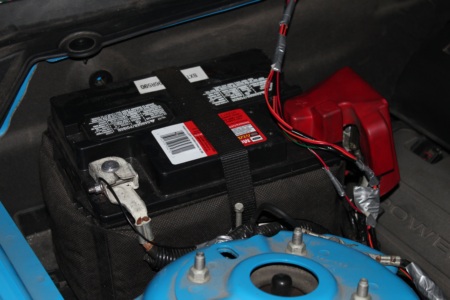
The sensor has a separate power and data interface. The power interface is accessible via screw terminals once the back plate of the sensor has been removed. Only the first two terminals (+24V and GND) need to be wired to use the sensor as its used in this project. The wires are then routed through a cable gland to the exterior of the sensor. We found that an ethernet cable with the ends cut off works well for the power cable. The sensor operates on 24 volt power. This presents some difficulty as the car operates on 12 volts. To overcome this, a boost converter is fed from battery power and its output is used to power the sensor with 24 volts. Do not wire the battery and sensor power directly together: a fuse should be used and at the least, a quick-release connector should be used.
The sensor uses a non-standard command set for communications via the RS232 interface. A list of commands is available on the sensor’s data sheet. The basic syntax for a command is as follows:
{one-byte command} {space} {newline} {carriage return}
The command set and data parsing is implemented in the sensor module Arduino code, so one need not worry about figuring out the sensor’s command set unless they need to use a very specific functionality of the sensor.
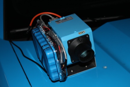
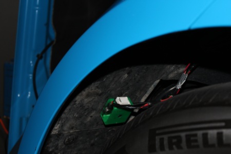
This project uses a custom sensor module to detect traction. The sensor module resides in the wheel well and collects ambient temperature, humidity and tire temperature. The sensor board has provisions for dust density measurement, but at the time of this writing that feature is not available. The module also includes a level shifter to transcode messages to and from the laser sensor.
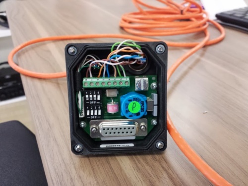
The sensor board is based around an Arduino Mega, and is made from a protoboard. This allows the board to easily be replicated by hobbyists without the need to order custom PCBs. The first step in making he sensor board is to solder headers to the protoboard such that an Arduino Mega can plug into the sensor board. From here, we will connect the sensors to the appropriate pins. Power for the board is provided via the FTDI cable.
RESET → FTDI DTR 5V → FTDI 5V, MAX232 16, DHT V+, MELEXIS V+, GND → FTDI GND, FTDI CTS, MAX232 15, DHT V-, RS232 GND, MELEXIS V- 22 → DHT SIGNAL SCL → MELEXIS SCL, use pull up resistors on SCL and SDA SDA → MELEXIS SDA TX1 → MAX232 11 RX1 → MAX232 12 RX2 → FTDI TX TX2 → FTDI RX
A 1μF filter cap should be used between the 5V and GND.
Wire the MAX232 as specified in the data sheet, specifically: MAX232 13 → RS232 RX MAX232 14 → RS232 TX
The firmware for the board is available in the brakedist repo. The firmware outputs/receives debug messages via Serial0, RS232 via Serial1 and JSON sensor readings via Serial2. The communication with the Android device is all done through Serial2, therefore when the sensor board is deployed on a vehicle, it is only necessary to connect the FTDI device via USB. The Arduino built in USB device need only be connected to flash the device or debug the sensor board.
The firmware requires the following libraries: i2Cmaster (http://homepage.hispeed.ch/peterfleury/avr-software.html) DHTlib aJson
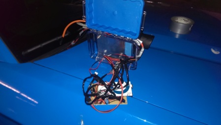
The sensor board is housed in a Pelican Box which is bolted onto the side of the LiDAR mount. This makes for the shortest wire routing possible. The Pelican box is drilled with the same hole pattern template use for the LiDAR mount. The sensors are attached to a sensor mount that is magnetically held in the wheel well. The CAD files for the mount can be found in the brakedist repo and can easily be printed on a hobbyist 3D printer. To assemble the sensor module, simply glue the humidity sensor to the exterior of the housing, glue the infrared temperature sensor into its hole and glue two or more appropriately sized magnets into their cavities (there are four magnet cavities, but in practice two magnets sufficed). It is recommended for ease of assembly and disassembly that all connections to the board be made with pluggable connectors.
The Android software for the project takes in sensor readings from the sensor module and the LiDAR unit and with the addition of real-time OpenXC data, computes the safe following distance. Should a driver follow too closely, the Android software alerts them by manipulating the display of the Retro Gauge.
The Android software consists of five major components:
Main Activity The main activity is responsible for controlling the app lifecycle and also for controlling the user interface. Additionally, the main activity instantiates all the other classes and has ultimate control over program execution.
Compute Distance Compute Distance is the core class for the brake distance tracking project. Compute distance stores the states of all the sensors and runs in its own thread, continuously updating the sensor values and computing the brake distance based on these values.
Data Logger The data logger is a class that keeps a record of all the state of the compute distance variables. It stores these values as JSON strings with a timestamp appended. These logs can then be used to improve the algorithms used to detect traction and compute braking distance. The data logger class was written to be flexible and can therefore be used with other projects in need os a simple data logger.
Serial Link The serial link class abstracts away the low level communications with the sensor module, Retro Gauge and LiDAR. There are two instances of Serial Link which are members of the Compute Distance instance. Each serial link is implemented in its own thread and constantly checks for new data and writes outgoing data. The serial link class makes use of streams to both make writing to the file system more seamless and also to handle message buffering.
JSON Transcoder The JSON transcoder class consists of a number of static methods and variables used to convert to and from Java objects used in the compute distance class and JSON strings. This class is based on a streaming JSON parser and therefore could be expanded to parse very long JSON messages and process the data as it is read.
The Android software makes use of the following libraries: OpenXC Jackson JSON FTDriver
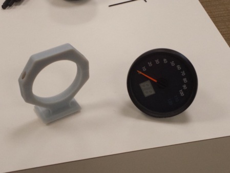
The user interface for this project is based on the Retro Gauge OpenXC project by Dave Evans. The gauge is modified with a different gauge face and also lacks the numerical readeout of Dave’s original design. As part of this project a modular gauge mount was also designed. This mount pairs with Chad Bean’s modular docking project and allows for a seamless integration into a vehicle with a modular dock already installed. The mount is 3D printed and has two halves that bolt together. The CATPart files and stl files for the gauge mount can be found int the brakedist repo.